|
Solenoids Kits
Golf Cart Solenoid Information:
 Oddly enough, to reliably conduct all this current and continue to function thousands and thousands of times, most solenoids have a relatively simple design. A steel plunger with a thick plate on one end is surrounded by a coil of thin wire wrapped many times, kind of like a fat spool of thread. When a small amount of battery juice is put across the thin wire, the magnetic field created by the coil throws the steel plunger and plate into two large bolts that stick out of the side of the solenoid case. The two large bolts, or steel studs, and the plate conduct the high current needed to power the starter or golf car motor. The great advantage to this high amp switch is the plate throws very quickly against the large studs, thereby minimizing the electrical arcing created when connecting high amperage. Picture when you pull a plug out of the wall when the appliance is still on. You see a spark at the wall receptacle. Inside a golf car solenoid this arcing occurs every time the car is stopped and started. It's easy to see why solenoids are the #1 problem in electric cars. In the early years of golf cars, there were all kinds and designs of multi-solenoid speed controllers. Reliably switching all the battery current required in those early years gave the manufacturers fits. Modern golf cars still have solenoids, but with the advent of electronic speed controllers and regen motors, it seems as though the solenoids do a little better these days. Today, new demands are placed on the solenoid because folks are lifting their golf cars with larger diameter tires and installing larger motors and controllers. This effectively creates the need for greater amperage draw to start the electric vehicle, to overcome inertia. These high currents also take a toll on the Forward & Reverse switch, which is designed to handle 300 amps, more or less. Regen motor controllers now effectively function as F&R switches by electronically directing the high amperage. The regen controller needs only a low amp signal from a dash mounted F&R toggle switch to correctly switch forward or reverse. Non-regen cars do not have this function so high amperage put through to the F&R switch can create problems. In some cases, installing larger power cables in the car can alleviate F&R problems. Standard battery cable is #6. Installing #4 cable and ends can help. In severe case, a multi-solenoid F&R switch can be installed in your car to replace the mechanical rotary switch. Multi-solenoid F&R switches were common in Harleys, Columbias, Pargos, Yamahas and other early electric and gas cars. They all used a key to change directions. That's because a key switch can handle the small amount of current needed to throw a solenoid. The solenoid does the heavy lifting, so to speak.  In this design, one solenoid becomes the Forward solenoid and the other becomes the Reverse solenoid. A 10 amp, 3 way key switch controls which solenoid energizes. Solenoids come in lots of designs with different metals used for the terminal studs and plate. Most common is copper, but years ago silver and silver plate was common. They also come in many different amperage ratings and voltage requirements needed to properly energize the coil so it functions as intended. Some solenoids are designed to work for short periods of time such as the starter solenoid in your automobile. These are intermittent duty solenoids. Golf cars require "continuous duty" solenoids because they are energized the entire time the car is under power. Auto style solenoids will work as a "continuous duty" solenoid for a while but they will prematurely fail. Lots of things go wrong with these switches. Obviously, the high amps create a lot of arcing at the stud/plate interface inside the solenoid. Even though the plate is designed to slightly rotate with each throw, eventually the stud/plate connection deteriorates, sometimes to the point where it breaks down completely. This is evidenced by the solenoid clicking and sometimes working (car moves), and sometimes not working. Complete failure is around the corner though. Electric cars are funny. Sometimes when there is a problem here, the failure shows up over there. Loose connections anywhere the heavy battery cables attach (i.e. –the speed switch, the motor, the batteries, F&R switch, even on the solenoids itself) creates a lot of heat build up and, if loose enough, arcing. Remember DC current is what welders use. When a sufficient air gap is established the DC arc melts steel. Solenoids and lead battery posts don't stand chance. Keep all cable connections in the car clean and tight. Inspect them at least once a year. Tightness is not as critical with the small control wires, the control circuit as it is called. Nevertheless, these connections must also be clean and tight. Another reason solenoids don't work is because the energizing current just doesn't get to the coil. In order that electricity gets to the solenoid winding, it must first pass through the key switch and usually several small micro (or limit) switches often found on the F&R switch and on the accelerator linkage. If any of these switches have failed or if the wires interlinking them have broken or are loose, then current cannot get to the solenoid. Some of these switches are position sensitive. If one gets out of adjustment, even though it works ok, it cannot function.  The last type of solenoid failure results when the internal plate and studs freeze to each other. In other words, the solenoid works ok, but doesn't stop working when the pedal is released. This results in the car creeping on its own when the shifter is in F or R. Sticky solenoids are more common in the older resistor style cars, but this condition, if not recognized and repaired, can be a fire hazard and at a minimum, cause the battery pack to drain. Lots of folks have seen the result of a sticky solenoid. The resistor coils glow red hot, hence the fire hazard, and why this glowing condition drains the batteries. If this situation happens to you, just shift into neutral each time you stop. Get it fixed right away! Remember that arcing we mentioned earlier? Now that arcing is occurring at the F&R switch, not the solenoid. The F&R is not designed to handle this condition. 1. How To Check Your Golf Cart for A bad Solenoid Answers: 1. How To Check Your Golf Cart for A bad Solenoid In this article as you may have guessed I am going to explain how to check a solenoid for problems. First you will need a couple of tools, a voltmeter and typically a ½” wrench. On a typical solenoid there are four post called terminals. There are usually two large and two small. Battery voltage is applied to the two small terminals to activate the solenoid which then connects the two large terminals together. From time to time the two large terminals get buggered up and the solenoid needs to be replaced. To check the solenoid is fairly simple though. First thing we need to do is disconnect any cables from the two large terminals. Be sure to wrap the cable ends in tape and keep them separate from each other. Then set your voltmeter to OHMS and place a probe on each large terminals(see first image below). With the key off and the cart in a neutral position there should be no reading. Now with the cart in foreword position and key on step on the accelerator, you should hear a click coming from the solenoid, if you do then set you voltmeter to OHMS and place a probe on each large terminals(see second image below). You should have a reading of 0 to 0.4 ohms. Anything higher and it means that solenoid has buggered up contacts and should be replaced. If you did not here a click coming from your solenoid then grab your voltmeter and set it to dc volts on the 200 scale and place a probe on each of the small terminals. With the key on and the cart in foreword step on the accelerator. You should see pretty close to full battery voltage. If you do see full battery voltage and there is no click, the coil inside the solenoid has failed and will need to be replaced. If your meter remains at 0 then there is a problem somewhere else in the cart. NOTES: When buying a new solenoid besure to buy one that matches your carts voltage, most golf carts are either 36v or 48v. It will usally tell you on the side of the solenoid what voltage it is. If you use the D&D Motor Systems Choosing A Motor tool then you can be assured to get the right parts every time. 2. How do I tell if my Golf Cart Solenoid is not working? Next to batteries, the most misunderstood part of a gas or electric car is the Golf Cart Solenoid. A Golf Cart Solenoid is nothing more than a switch. Switches are normally mechanically activated devices similar to a light or key switch. These types of switches require manual or mechanical activation. Golf Cart Solenoids are just switches activated by an external electrical input. It does not matter whether its a Club Car Solenoid or an EZ-GO Solenoid, a Golf Cart Solenoids sole purpose is to make and break an electrical circuit on demand. The term "contactor" is also used to describe a Golf Cart Solenoid. A Golf Cart Solenoid has two basic circuits, the Primary and Secondary circuit. In the Primary, or activation circuit, you have two components, the activation wiring and the internal primary coil. When subjected to electric voltage the internal primary coil activates, bringing two contact points together to allow an electric current to pass through the Secondary circuit. The coil requires both the positive and negative potentials for electric voltage to pass through it and activate. Most cars activate the Golf Cart Solenoid with normal battery pack voltage. However, be aware there are some older model cars that use a system of "tapped" voltage and the Golf Cart Solenoids must be connected to a specific voltage. Taps are just different connecting points on the battery pack. The Secondary, or power circuit, is the circuit being activated by the Golf Cart Solenoids coil. This circuit consists of large power contacts inside the Golf Cart solenoid that allow a heavy load of electric current to flow to the motor or starter/generator when activated. Any time you are working with a car's electrical system, be sure you have the correct wiring diagram for the application you are testing! In the accompanying diagram, the connection terminals on the Golf Car Solenoid have been numbered 1 though 4 for ease of identification purposes only.
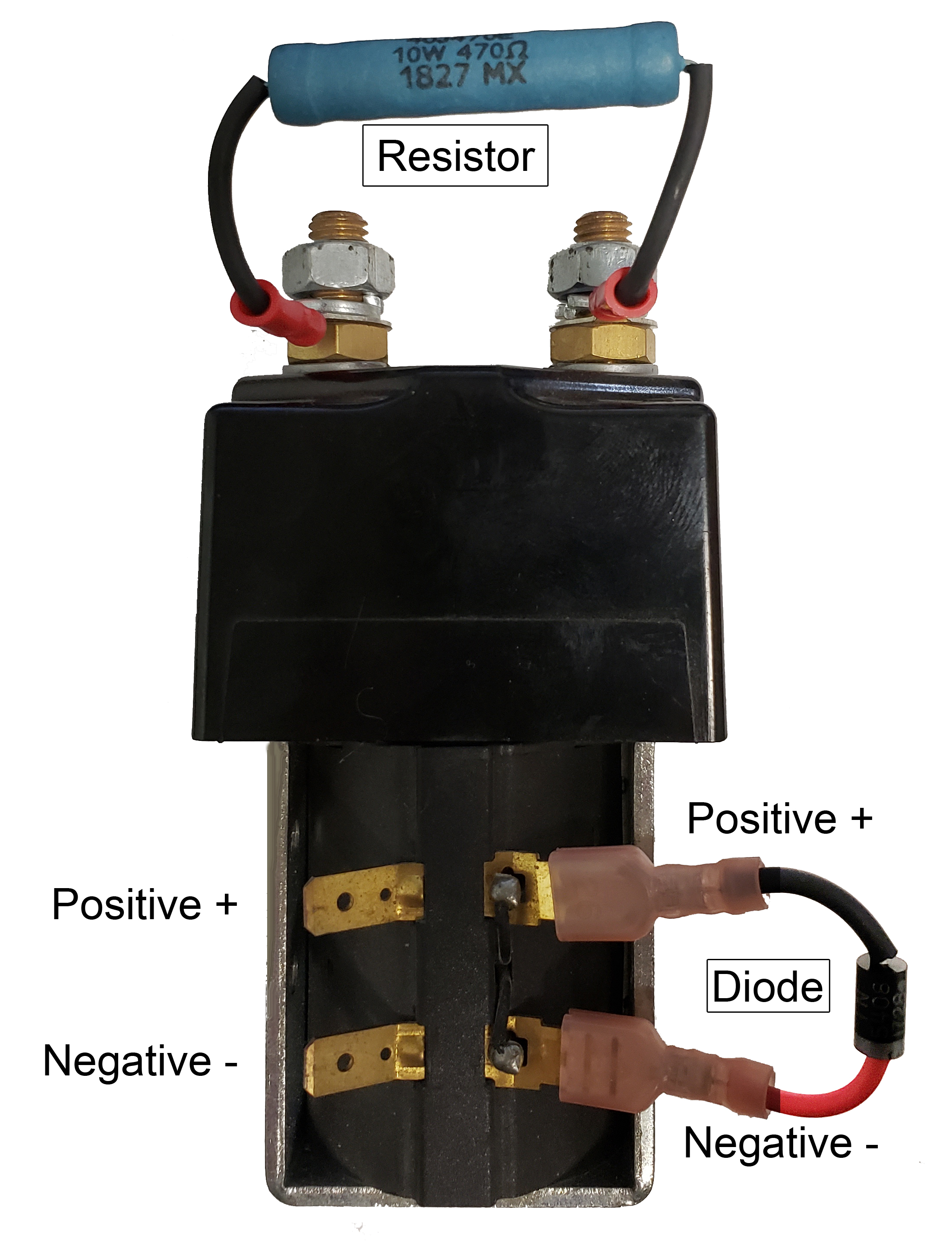
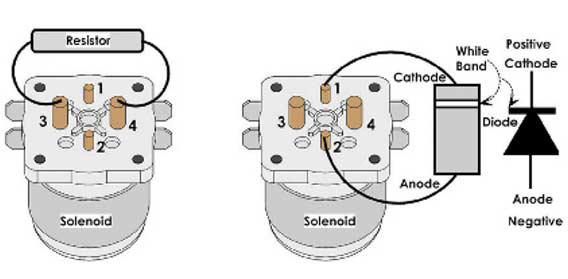 In the diagram, there are some other items that may or may not be on your car system, a diode and resistor. Not all applications use the diode and resistor, and that is why it is important to determine the year, make, and model of your car.
The diode functions as a buffer to catch voltage spikes in the Primary circuit. The resistor (250 ohms) is used to pre-charge the capacitor bank in the car controller if it uses this system. The resistor will connect to the Secondary circuit's large terminals. Again, use the correct diagram for the system you are working on. 3. How do I trouble shoot my solenoid?
1) The car will not run. A) Does the Club Car Solenoid or EZ-GO Solenoid make a "clicking" sound? Make the connection just like this. Positive connection at terminal #2. Negative connection at terminal #1. If your car uses the diode in the solenoid system, make sure you make the proper connections and orientation as the diode is polarity-sensitive! This is different between the Club Car Solenoid and the EZ-GO Solenoid. Secondary Circuit (power) Safety
|
| D&D Motor Systems, Inc |