Browse
Dealer
High Performance DC Motors and Controllers
Buy a Golf Motor/
Golf Controller
Frequently Asked Questions
General Motor Questions
- 1. Do D&D Motors work on 36V and 48V golf carts?
- 2. How do I install a D&D Motor?
- 3. Do I have a Series or Regen motor?
- 4. The speed sensor on a D&D motor doesn't connect to my golf cart speed sensor cable. What should I do?
- 5. What to do if I can't get my old motor off the transaxle?
- 6. What voltage are the batteries in my Golf Cart?
- 7. Is my D&D Motor for Club Car Golf Carts missing an L-bracket?
- 8. Why do D&D motors for GEM carts only have one connection?
- 9. How can I determine what mounting pattern and shaft type I need for my Golf Cart motor?
- 10. Why are my forward and reverse controls flipped after motor installation?
- 11. How do I program my controller?
- 12. What batteries should I buy for my golf cart?
- 13. My old motor had a rubber insert in the shaft, does my D&D motor need this?
- 14. How do I upgrade my V-Glide controller to a solid state controller?
- 15. Why are new high performance Golf Cart Motors better than 3rd party refurbished motors?
- 16. What is a DC Motor?
- 17. What Is a Shunt or Regen or SEPEX Motor?
- 18. What Are Series DC Motors?
- 19. Pros and Cons of Using Series vs Seperately Excited (SEPEX) DC Motors
- 20. How Does An Electric DC Motor Work?
- 21. Why is it that many pump motors use tang drivers?
Speed Questions
General EV Questions
1. Do D&D Motors work on 36V and 48V golf carts?
All D&D golf cart motors work on 36V and 48V golf carts. After converting a golf cart from 36V to 48V the performance gain from a standard EZGO, Club Car, or Yamaha model is normally around 3-4mph. For 72V and other voltages, give us a call.
2. How do I install a D&D Motor?
Go to the Installation Videos page on our website for video tutorials on how to install your golf cart motor and controller. In addition, we recommend taking a picture of your old motor wiring before disconnecting. Your new D&D motor will be wired in the same exact way.
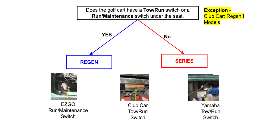
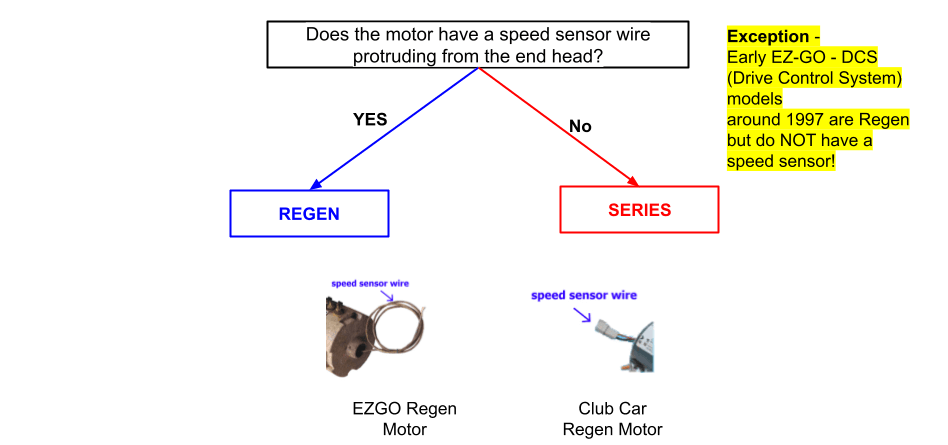
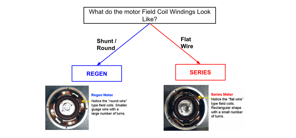
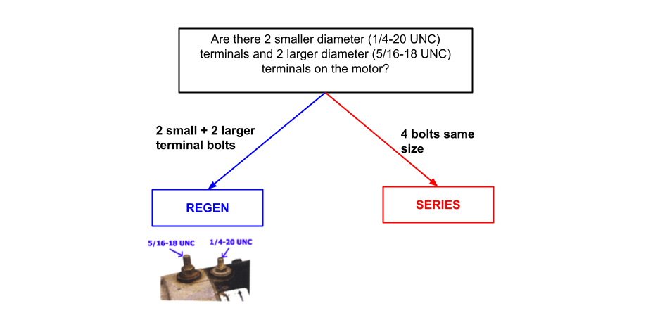
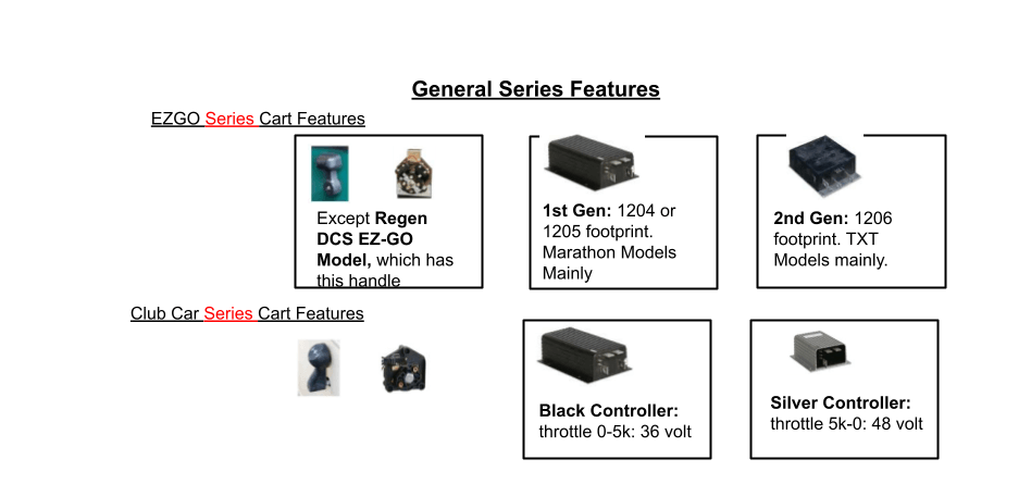
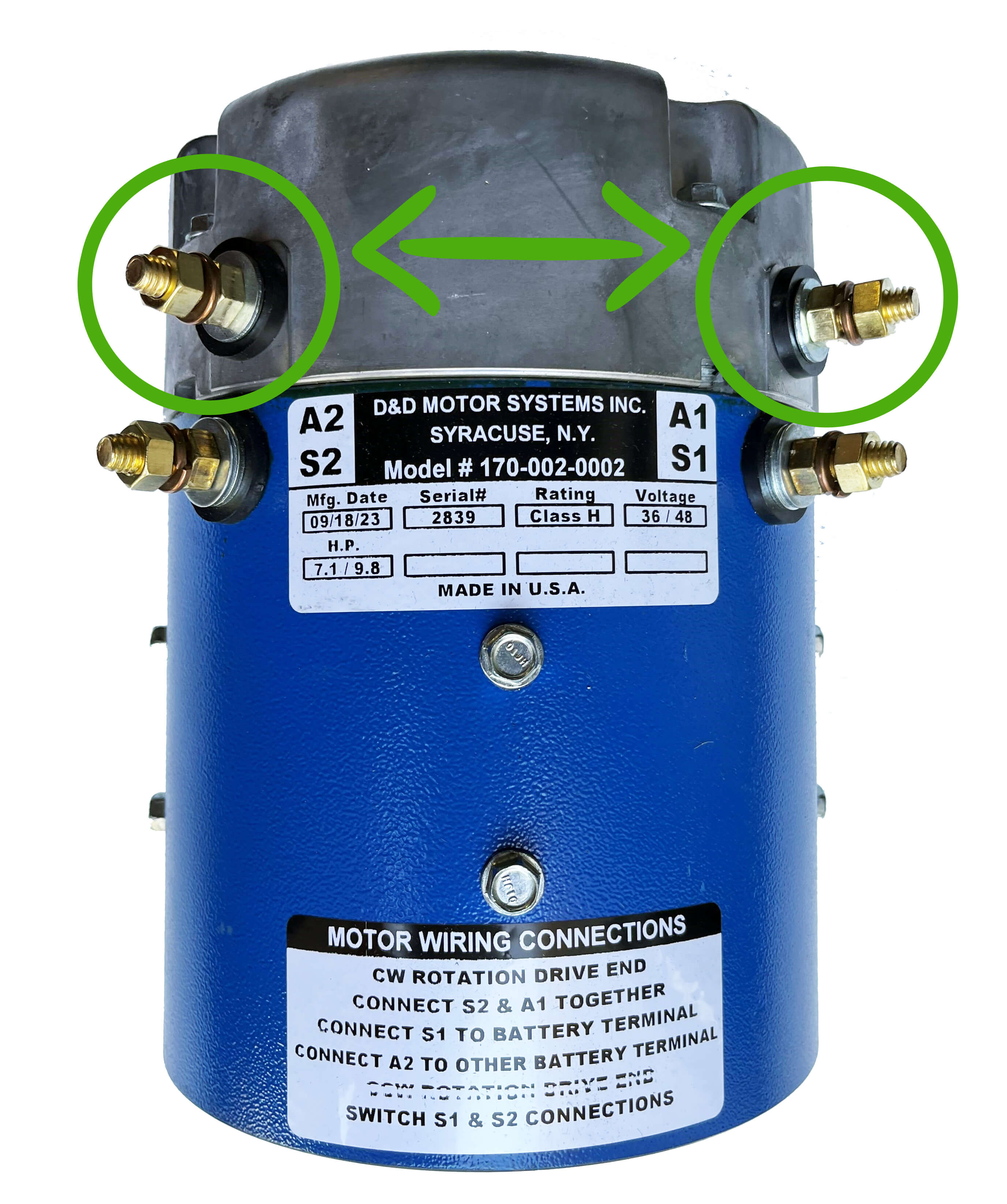
3. Do I have a Series or Regen motor?
Please follow the slides below to determine if your cart is Regen or Series. For security to be certain, confirm with at least 3 slides. Click on the arrows <> to go to the next slide.
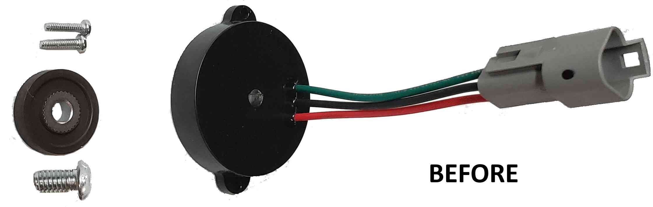
4. The speed sensor on a D&D motor doesn't connect to my golf cart speed sensor cable. What should I do?
You will need to cut off the connector at the end of the speed sensor on the D&D motor and strip the 3 wires. The wires on the D&D motor are Red, Green, and Black. Your speed sensor wires will now look like the image below. Now, strip the insulation from the 3 wires coming from the vehicle connector. Once this is done, twist together all wires with matching colors (ex. Red motor speed sensor wire with Red golf cart wire) and cover the exposed wire with electrical tape. If there is one mismatching wire color on the motor and golf cart, connect those two together, those will be your ground wires. Now your speed sensor is setup properly.
5. What to do if I can't get my old motor off the transaxle?
We recommend buying "PB Blaster Penetrant" to loosen up any corrosion or other issues stopping the motor from disconnecting. This can be purchased for about $10 from Home Depot. We recommend PB Blaster Penetrant over WD-40 because WD-40 does not protect against future corrosion like PB Blaster Permanent. Once purchased, spray liberally on the drive end head and mounting bolts of the old motor and wait 8 hours before attempting to remove the motor again.
6. What voltage are the batteries in my Golf Cart?
Golf cart batteries are either 6 volt, 8 volt, or 12 volt. You can tell the voltage based on how many water holes your battery has on the top. Multiply your battery voltage by the number of batteries in your golf cart to find your golf cart voltage. If your golf cart has 0 holes, then you probably have lithium batteries. You will need to read the battery label or look online to find your battery voltage. For more help, the video below may help.
| • 3 holes = 6 volts |
| • 4 holes = 8 volts |
| • 6 holes = 12 volts |
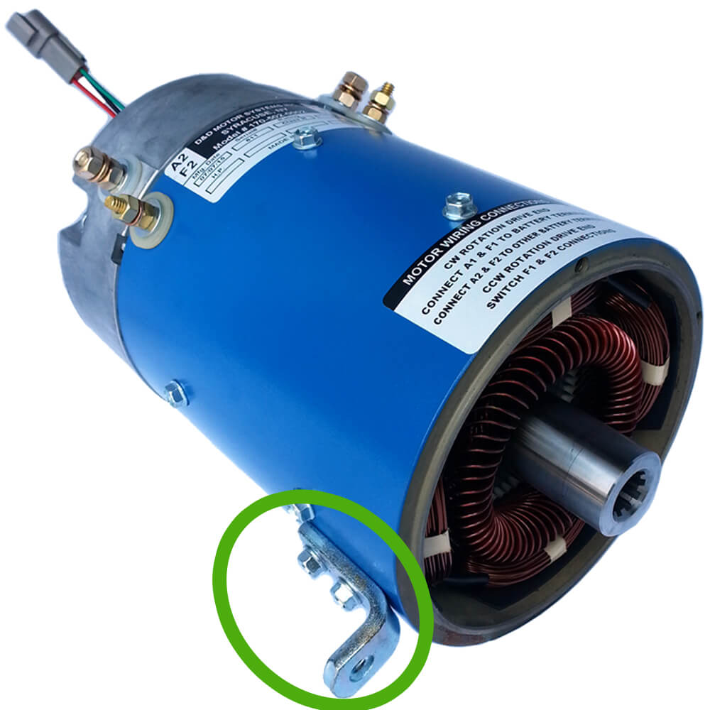
7. Is my D&D Motor for Club Car Golf Carts missing an L-bracket?
No. The L-bracket is required for connecting to the fourth hole on a Club Car Golf Cart mount. It is only needed for larger or higher torque motors that need additional support. Smaller D&D motors for Club Car Golf Carts do not need additional support, so the L-bracket is omitted. Image of L-Bracket below.
8. Why do D&D motors for GEM carts only have one connection?
Other GEM Cart motors sometimes have a heat sink connection in addition to the speed sensor connection on the top of the motor. D&D motors don't have a heat sink connection because it is not needed for our motors.
9. How can I determine what mounting pattern and shaft type I need for my Golf Cart motor?
The "Choose a Motor Tool" accounts for shaft type and mounting pattern when providing motor options. Mounting pattern and shaft are unique for each golf cart brand, so we recommend customers use the Choose a Motor Tool provide customers a good buying experience and correct motor options. Without going through our "Choose a Motor Tool", we cannot provide a customer warranty!!!
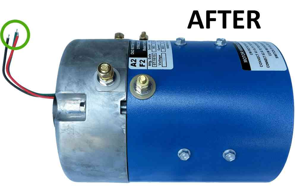
10. Why are my forward and reverse controls flipped after motor installation?
This sometimes occurs when installing a D&D motor to replace an older motor. To fix this, swap the motor connections on the A1 and A2 terminals. Image of terminals to flip below.
11. How do I program my controller?
For Alltrax controllers, click here to download the "Alltrax Toolkit" software. This software allows you to customize your controller performance. The user manual is also available at the link. If you need additional tech support, call Alltrax's tech help line for world class customer support at 541-476-3565. For Navitas controllers, download the "Navitas" app on the app store. If you need additional tech support for Navitas, call 519-442-0948
This guide on how to setup your app and customize your Golf Cart
12. What batteries should I buy for my golf cart?
You need to purchase batteries that have a maximum discharge of 500 amps. The type of battery (Lithium, Lead-Acid, etc.) is independent of Max Discharge. Navigate to our "Beginners Guide to Motors" for more details about batteries.
13. My old motor had a rubber insert in the shaft, does my D&D motor need this?
No. D&D motors use higher quality shafts made in the USA. This allows our motors to run quietly without an additional rubber insert.
14. How do I upgrade my V-Glide controller to a solid state controller?
Upgrading a V-Glide controller to a solid state controller will take a few hours and can be a bit complex, but it will increase your max controller amps from 200 to the max amps of the new controller (up to 600 amps). Your performance will increase significantly. We recommend following this youtube video walkthrough explaining exactly how to do this process.
This video shows a customer replacing his V-Glide controller, as well as replacing an old motor with a new D&D motor.
15. Why are new high performance Golf Cart Motors better than 3rd party refurbished motors?
There are a multitude of reasons behind buying new high performance gold carts over 3rd party ones. Mainly when it comes to better performance, reliability, greater efficiency, its longer lifespan, and most importantly how customizable it is. A newer motor can be sorted out and customized to what you need for your vehicle setup, performance, and application.
16. What is a DC Motor?
A DC motor is an electric motor that runs on direct current (DC) electricity. DC motors were used to run machinery, often eliminating the need for a local steam engine or internal combustion engine. DC motors can operate directly from rechargeable batteries, providing the motive power for the first electric vehicles. Modern DC motors are nearly always operated in conjunction with power electronic devices. The brushed DC electric motor generates torque directly from DC power supplied to the motor by using internal commutation, stationary magnets (permanent or electromagnets), and rotating electrical magnets. Like all electric motors or generators, torque is produced by the principle of Lorentz force, which states that any current-carrying conductor placed within an external magnetic field experiences a torque or force known as Lorentz force. Advantages of a brushed DC motor include low initial cost, high reliability, and simple control of motor speed.
DC motors are commonly constructed with wound rotors and either wound or permanent magnet stators.
Wound Stators
The field coils have traditionally existed in four basic formats: separately excited (sepex), series-wound, shunt-wound, and a combination of the latter two; compound-wound. In a series wound motor, the field coils are connected electrically in series with the armature coils (via the brushes). In a shunt wound motor, the field coils are connected in parallel, or "shunted" to the armature coils. In a separately excited (sepex) motor the field coils are supplied from an independent source, such as a motor-generator and the field current is unaffected by changes in the armature current. The sepex system was sometimes used in DC traction motors to facilitate control of wheelslip.
Simple 2 pole DC Motor
When a current passes through the coil wound around a soft iron core, the side of the positive pole is acted upon by an upwards force, while the other side is acted upon by a downward force. According to Fleming's left hand rule, the forces cause a turning effect on the coil, making it rotate. To make the motor rotate in a constant direction, "direct current" commutators make the current reverse in direction every half a cycle (in a two-pole motor) thus causing the motor to continue to rotate in the same direction. A problem with the motor shown above is that when the plane of the coil is parallel to the magnetic field - i.e. when the rotor poles are 90 degrees from the stator poles, the torque is zero. In the pictures above, this occurs when the core of the coil is horizontal, the position it is just about to reach in the last picture on the right. The motor would not be able to start in this position. However, once it was started, it would continue to rotate through this position by momentum.
17. What Is a Shunt or Regen or SEPEX Motor?
The shunt motor is different from the series motor in that the field winding is connected in parallel with the armature instead of in series. You should remember from basic electrical theory that a parallel circuit is often referred to as a shunt. Since the field winding is placed in parallel with the armature, it is called a shunt winding and the motor is called a shunt motor. Figure 12-13 shows a diagram of a shunt motor. Notice that the field terminals are marked Fl and F2, and the armature terminals are marked Al andA2. You should notice in this diagram that the shunt field is represented with multiple turns using a thin line.
FIGURE 12-13 Diagram of DC shunt motor. Notice the shunt coil is identified as a coil of fine wire with many turns that is connected in parallel (shunt) with the armature.
FIGURE 12-14 Typical DC shunt motor. These motors are available in a variety of sizes. This motor is a 1 hp (approximately 8 in. tall).
The shunt winding is made of small-gauge wire with many turns on the coil. Since the wire is so small, the coil can have thousands of turns and still fit in the slots. The small-gauge wire cannot handle as much current as the heavy-gauge wire in the series field, but since this coil has many more turns of wire, it can still produce a very strong magnetic field. Figure 12-14 shows a picture of a DC shunt motor.
Shunt Motor Operation
A shunt motor has slightly different operating characteristics than a series motor. Since the shunt field coil is made of fine wire, it cannot produce the large current for starting like the series field. This means that the shunt motor has very low starting torque, which requires that the shaft load be rather small.
When voltage is applied to the motor, the high resistance of the shunt coil keeps the overall current flow low. The armature for the shunt motor is similar to the series motor and it will draw current to produce a magnetic field strong enough to cause the armature shaft and load to start turning. Like the series motor, when the armature begins to turn, it will produce back EMF. The back EMF will cause the current in the armature to begin to diminish to a very small level. The amount of current the armature will draw is directly related to the size of the load when the motor reaches full speed. Since the load is generally small, the armature current will be small. When the motor reaches full rpm, its speed will remain fairly constant.
Controlling the Speed
When the shunt motor reaches full rpm, its speed will remain fairly constant. The reason the speed remains constant is due to the load characteristics of the armature and shunt coil. You should remember that the speed of a series motor could not be controlled since it was totally dependent on the size of the load in comparison to the size of the motor. If the load was very large for the motor size, the speed of the armature would be very slow. If the load was light compared to the motor, the armature shaft speed would be much faster, and if no load was present on the shaft, the motor could run away.
The shunt motor's speed can be controlled. The ability of the motor to maintain a set rpm at high speed when the load changes is due to the characteristic of the shunt field and armature. Since the armature begins to produce back EMF as soon as it starts to rotate, it will use the back EMF to maintain its rpm at high speed. If the load increases slightly and causes the armature shaft to slow down, less back EMF will be produced. This will allow the difference between the back EMF and applied voltage to become larger, which will cause more current to flow. The extra current provides the motor with the extra torque required to regain its rpm when this load is increased slightly.
The shunt motor's speed can be varied in two different ways. These include varying the amount of current supplied to the shunt field and controlling the amount of current supplied to the armature. Controlling the current to the shunt field allows the rpm to be changed 10-20% when the motor is at full rpm.
This type of speed control regulation is accomplished by slightly increasing or decreasing the voltage applied to the field. The armature continues to have full voltage applied to it while the current to the shunt field is regulated by a rheostat that is connected in series with the shunt field. When the shunt field's current is decreased, the motor's rpm will increase slightly. When the shunt field's current is reduced, the armature must rotate faster to produce the same amount of back EMF to keep the load turning. If the shunt field current is increased slightly, the armature can rotate at a slower rpm and maintain the amount of back EMF to produce the armature current to drive the load. The field current can be adjusted with a field rheostat or an SCR current control.
The shunt motor's rpm can also be controlled by regulating the voltage that is applied to the motor armature. This means that if the motor is operated on less voltage than is shown on its data plate rating, it will run at less than full rpm. You must remember that the shunt motor's efficiency will drop off drastically when it is operated below its rated voltage. The motor will tend to overheat when it is operated below full voltage, so motor ventilation must be provided. You should also be aware that the motor's torque is reduced when it is operated below the full voltage level.
Since the armature draws more current than the shunt field, the control resistors were much larger than those used for the field rheostat. During the 1950s and 1960s SCRs were used for this type of current control. The SCR was able to control the armature current since it was capable of controlling several hundred amperes. In Chapter 11 we provided an in-depth explanation of the DC motor drive.
Torque Characteristics
The armature's torque increases as the motor gains speed due to the fact that the shunt motor's torque is directly proportional to the armature current. When the motor is starting and speed is very low, the motor has very little torque. After the motor reaches full rpm, its torque is at its fullest potential. In fact, if the shunt field current is reduced slightly when the motor is at full rpm, the rpm will increase slightly and the motor's torque will also in-crease slightly. This type of automatic control makes the shunt motor a good choice for applications where constant speed is required, even though the torque will vary slightly due to changes in the load. Figure 12-15 shows the torque/speed curve for the shunt motor. From this diagram you can see that the speed of the shunt motor stays fairly constant throughout its load range and drops slightly when it is drawing the largest current.
FIGURE 12-15 A curve that shows the armature current versus the armature speed for a shunt motor. Notice that the speed of a shunt motor is nearly constant.
FIGURE 12-16 Diagram of a shunt motor connected to a reversing motor starter. Notice that the shunt field is connected across the armature and it is not reversed when the armature is reversed.
Reversing the Rotation
The direction of rotation of a DC shunt motor can be reversed by changing the polarity of either the armature coil or the field coil. In this application the armature coil is usually changed, as was the case with the series motor. Figure 12-16 shows the electrical diagram of a DC shunt motor connected to a forward and reversing motor starter. You should notice that the Fl and F2 terminals of the shunt field are connected directly to the power supply, and the Al and A2 terminals of the armature winding are connected to the reversing starter.
When the FMS is energized, its contacts connect the Al lead to the positive power supply terminal and the A2 lead to the negative power supply terminal. The Fl motor lead is connected directly to the positive terminal of the power supply and the F2 lead is connected to the negative terminal. When the motor is wired in this configuration, it will begin to run in the forward direction.
When the RMS is energized, its contacts reverse the armature wires so that the Al lead is connected to the negative power supply terminal and the A2 lead is connected to the positive power supply terminal. The field leads are connected directly to the power supply, so their polarity is not changed. Since the field's polarity has remained the same and the armature's polarity has reversed, the motor will begin to rotate in the reverse direction. The control part of the diagram shows that when the FMS coil is energized, the RMS coil is locked out.
Installing a Shunt motor
A shunt motor can be installed easily. The motor is generally used in belt-drive applications. This means that the installation procedure should be broken into two sections, which include the mechanical installation of the motor and its load, and the installation of electrical wiring and controls.
When the mechanical part of the installation is completed, the alignment of the motor shaft and the load shaft should be checked. If the alignment is not true, the load will cause an undue stress on the armature bearing and there is the possibility of the load vibrating and causing damage to it and the motor. After the alignment is checked, the tension on the belt should also be tested. As a rule of thumb, you should have about V2 to 1/4 inch of play in the belt when it is properly tensioned.
Several tension measurement devices are available to determine when a belt is tensioned properly. The belt tension can also be compared to the amount of current the motor draws. The motor must have its electrical installation completed to use this method.
The motor should be started, and if it is drawing too much current, the belt should be loosened slightly but not enough to allow the load to slip. If the belt is slipping, it can be tightened to the point where the motor is able to start successfully and not draw current over its rating.
The electrical installation can be completed before, after, or during the mechanical installation. The first step in this procedure is to locate the field and armature leads in the motor and prepare them for field connections. If the motor is connected to magnetic or manual across the line starter, the Fl field coil wire can be connected to the Al armature lead and an interconnecting wire, which will be used to connect these leads to the Tl terminal on the motor starter. The F2 lead can be connected to the A2 lead and a second wire, which will connect these leads to the T2 motor starter terminal.
When these connections are completed, field and armature leads should be replaced back into the motor and the field wiring cover or motor access plate should be replaced. Next the DC power supply's positive and negative leads should be connected to the motor starter's LI and L2 terminals, respectively.
After all of the load wires are connected, any pilot devices or control circuitry should be installed and connected. The control circuit should be tested with the load voltage disconnected from the motor. If the control circuit uses the same power source as the motor, the load circuit can be isolated so the motor will not try to start by disconnecting the wire at terminal L2 on the motor starter. Operate the control circuit several times to ensure that it is wired correctly and operating properly. After you have tested the control circuit, the lead can be replaced to the L2 terminal of the motor starter and the motor can be started and tested for proper operation. Be sure to check the motor's voltage and current while it is under load to ensure that it is operating correctly. It is also important to check the motor's temperature periodically until you are satisfied the motor is operating correctly.
If the motor is connected to a reversing starter or reduced-voltage starting circuit, their operation should also be tested. You may need to read the material in Section 15.3.6 to fully understand the operation of these methods of starting the motor using reduced-voltage methods. If the motor is not operating correctly or develops a fault, a troubleshooting procedure should be used to test the motor and locate the problem.
Troubleshooting
When a DC shunt motor develops a fault, you must be able to locate the problem quickly and return the motor to service or have it replaced. The most likely problems to occur with the shunt motor include loss of supply voltage or an open in either the shunt winding or the armature winding. Other problems may arise that cause the motor to run abnormally hot even though it continues to drive the load. The motor will show different symptoms for each of these problems, which will make the troubleshooting procedure easier.
When you are called to troubleshoot the shunt motor, it is important to determine if the problem occurs while the motor is running or when it is trying to start. If the motor will not start, you should listen to see if the motor is humming and trying to start. When the supply voltage has been interrupted due to a blown fuse or a de-energized control circuit, the motor will not be able to draw any current and it will be silent when you try to start it. You can also determine that the supply voltage has been lost by measuring it with a voltmeter at the starter's LI and L2 terminals. If no voltage is present at the load terminals, you should check for voltage at the starter's Tl and T2 terminals. If voltage is present here but not at the load terminals, it indicates that the motor starter is de-energized or defective. If no voltage is present at the Tl and T2 terminals, it indicates that supply voltage has been lost prior to the motor starter. You will need to check the supply fuses and the rest of the supply circuit to locate the fault.
If the motor tries to start and hums loudly, it indicates that the supply voltage is present. The problem in this case is probably due to an open field winding or armature winding. It could also be caused by the supply voltage being too low.
The most likely problem will be an open in the field winding since it is made from small-gauge wire. The open can occur if the field winding draws too much current or develops a short circuit between the insulation in the coils. The best way to test the field is to remove supply voltage to the motor by opening the disconnect or de-energizing the motor starter. Be sure to use a lockout when you are working on the motor after the disconnect has been opened. The lockout is a device that is placed on the handle of the disconnect after the handle is placed in the off position, and it allows a padlock to be placed around it so it cannot be removed until the technician has completed the work on the circuit. If lockout has extra holes, additional padlocks can be placed on it by other technicians who are also working on this system. This ensures that the power cannot be returned to the system until all technicians have removed their padlocks. The lockout will be explained in detail in the chapter on motor controls later in this text.
After power has been removed, the field terminals should be isolated from the armature coil. This can be accomplished by disconnecting one set of leads where the field and armature are connected together. Remember that the field and armature are connected in parallel and if they are not isolated, your continuity test will show a completed circuit even if one of the two windings has an open.
When you have the field coil isolated from the armature coil, you can proceed with the continuity test. Be sure to use the R X 1k or R X 10k setting on the ohmmeter because the resistance in the field coil will be very high since the field coil may be wound from several thousand feet of wire. If the field winding test indicates the field winding is good, you should continue the procedure and test the armature winding for continuity.
The armature winding test may show that an open has developed from the coil burning open or from a problem with the brushes. Since the brushes may be part of the fault, they should be visually inspected and replaced if they are worn or not seating properly. If the commutator is also damaged, the armature should be removed, so the commutator can be turned down on a lathe.
If either the field winding or the armature winding has developed an open circuit, the motor will have to be removed and replaced. In some larger motors it will be possible to change the armature by itself rather than remove and replace the entire motor. If the motor operates but draws excessive current or heats up, the motor should be tested for loose or shorting coils. Field coils may tend to come loose and cause the motor to vibrate and overheat, or the armature coils may come loose from their slots and cause problems. If the motor continues to overheat or operate roughly, the motor should be removed and sent to a motor rebuilding shop so that a more in-depth test may be performed to find the problem before the motor is permanently damaged by the heat.
18. What Are Series DC Motors?
Series Motor Diagram
The series motor provides high starting torque and is able to move very large shaft loads when it is first energized. Figure 12-10 shows the wiring diagram of a series motor. From the diagram you can see that the field winding in this motor is wired in series with the armature winding. This is the attribute that gives the series motor its name.
Since the series field winding is connected in series with the armature, it will carry the same amount of current that passes through the armature. For this reason the field is made from heavy-gauge wire that is large enough to carry the load. Since the wire gauge is so large, the winding will have only a few turns of wire. In some larger DC motors, the field winding is made from copper bar stock rather than the conventional round wire used for power distribution. The square or rectangular shape of the copper bar stock makes it fit more easily around the field pole pieces. It can also radiate more easily the heat that has built up in the winding due to the large amount of current being carried.
FIGURE 12-10 Electrical diagram of series motor. Notice that the series field is identified as S1 and S2.
The amount of current that passes through the winding determines the amount of torque the motor shaft can produce. Since the series field is made of large conductors, it can carry large amounts of current and produce large torques. For example, the starter motor that is used to start an automobile's engine is a series motor and it may draw up to 500 A when it is turning the engine's crankshaft on a cold morning. Series motors used to power hoists or cranes may draw currents of thousands of amperes during operation.
The series motor can safely handle large currents since the motor does not operate for an extended period. In most applications the motor will operate for only a few seconds while this large current is present. Think about how long the starter motor on the automobile must operate to get the engine to start. This period is similar to that of industrial series motors.
Series Motor Operation
Operation of the series motor is easy to understand. In Fig. 12-10 you can see that the field winding is connected in series with the armature winding. This means that power will be applied to one end of the series field winding and to one end of the armature winding (connected at the brush).
When voltage is applied, current begins to flow from negative power supply terminals through the series winding and armature winding. The armature is not rotating when voltage is first applied, and the only resistance in this circuit will be provided by the large conductors used in the armature and field windings. Since these conductors are so large, they will have a small amount of resistance. This causes the motor to draw a large amount of current from the power supply. When the large current begins to flow through the field and armature windings, it causes a strong magnetic field to be built. Since the current is so large, it will cause the coils to reach saturation, which will produce the strongest magnetic field possible.
Producing Back EMF
The strength of these magnetic fields provides the armature shafts with the greatest amount of torque possible. The large torque causes the armature to begin to spin with the maximum amount of power. When the armature begins to rotate, it begins to produce voltage. This concept is difficult for some students to understand since the armature is part of the motor at this time.
You should remember from the basic theories of magnetism that anytime a magnetic field passes a coil of wire, a current will be produced. The stronger the magnetic field is or the faster the coil passes the flux lines, the more current will be generated. When the armature begins to rotate, it will produce a voltage that is of opposite polarity to that of the power supply. This voltage is called back voltage, back EMF (electromotive force), or counter EMF. The overall effect of this voltage is that it will be subtracted from the supply voltage so that the motor windings will see a smaller voltage potential.
When Ohm's law is applied to this circuit, you will see that when the voltage is slightly reduced, the current will also be reduced slightly. This means that the series motor will see less current as its speed is increased. The reduced current will mean that the motor will continue to lose torque as the motor speed increases. Since the load is moving when the armature begins to pick up speed, the application will require less torque to keep the load moving. This works to the motor's advantage by automatically reducing the motor current as soon as the load begins to move. It also allows the motor to operate with less heat buildup.
This condition can cause problems if the series motor ever loses its load. The load could be lost when a shaft breaks or if a drive pin is sheared. When this occurs, the load current is allowed to fall to a minimum, which reduces the amount of back EMF that the armature is producing. Since the armature is not producing a sufficient amount of back EMF and the load is no longer causing a drag on the shaft, the armature will begin to rotate faster and faster. It will continue to increase rotational speed until it is operating at a very high speed. When the armature is operating at high speed, the heavy armature windings will be pulled out of their slots by centrifugal force. When the windings are pulled loose, they will catch on a field winding pole piece and the motor will be severely damaged. This condition is called runaway and you can see why a DC series motor must have some type of runaway protection. A centrifugal switch can be connected to the motor to de-energize the motor starter coil if the rpm exceeds the set amount. Other sensors can be used to de-energize the circuit if the motor's current drops while full voltage is applied to the motor. The most important part to remember about a series motor is that it is difficult to control its speed by external means because its rpm is determined by the size of its load. (In some smaller series motors, the speed can be controlled by placing a rheostat in series with the supply voltage to provide some amount of change in resistance to control the voltage to the motor.)
Figure 12-11 shows the relationship between series motor speed and armature current. From this curve you can see that when current is low (at the top left), the motor speed is maximum, and when current increases, the motor speed slows down (bottom right). You can also see from this curve that a DC motor will run away if the load current is reduced to zero. (It should be noted that in larger series machines used in industry, the amount of friction losses will limit the highest speed somewhat.)
FIGURE 12-11 The relationship between series motor speed and the armature current.
Reversing the Rotation
The direction of rotation of a series motor can be changed by changing the polarity of either the armature or field winding. It is important to remember that if you simply changed the polarity of the applied voltage, you would be changing the polarity of both field and armature windings and the motor's rotation would remain the same.
FIGURE 12-12 DC series motor connected to forward and reverse motor starter.
Since only one of the windings needs to be reversed, the armature winding is typically used because its terminals are readily accessible at the brush rigging. Remember that the armature receives its current through the brushes, so that if their polarity is changed, the armature's polarity will also be changed. A reversing motor starter is used to change wiring to cause the direction of the motor's rotation to change by changing the polarity of the armature windings. Figure 12-12 shows a DC series motor that is connected to a re-versing motor starter. In this diagram the armature's terminals are marked Al and A2 and the field terminals are marked Sl and S2.
When the forward motor starter is energized, the top contact identified as F closes so the Al terminal is connected to the positive terminal of the power supply and the bottom F contact closes and connects terminals A2 and Sl. Terminal S2 is connected to the negative terminal of the power supply. When the reverse motor starter is energized, terminals Al and A2 are reversed. A2 is now connected to the positive terminal. Notice that S2 remains connected to the negative terminal of the power supply terminal. This ensures that only the armature's polarity has been changed and the motor will begin to rotate in the opposite direction.
You will also notice the normally closed (NC) set of R contacts connected in series with the forward push button, and the NC set of F contacts connected in series with the reverse push button. These contacts provide an interlock that prevents the motor from being changed from forward to reverse direction without stopping the motor. The circuit can be explained as follows: when the forward push button is depressed, current will flow from the stop push button through the NC R interlock contacts, and through the forward push button to the forward motor starter (FMS) coil. When the FMS coil is energized, it will open its NC contacts that are connected in series with the reverse push button. This means that if someone depresses the reverse push button, current could not flow to the reverse motor starter (RMS) coil. If the person depressing the push buttons wants to reverse the direction of the rotation of the motor, he or she will need to depress the stop push button first to de-energize the FMS coil, which will allow the NC F contacts to return to their NC position. You can see that when the RMS coil is energized, its NC R contacts that are connected in series with the forward push button will open and prevent the current flow to the FMS coil if the forward push button is depressed. You will see a number of other ways to control the FMS and RMS starter in later discussions and in the chapter on motor controls.
Installing and Troubleshooting
Since a series motor has only two leads brought out of the motor for installation wiring, this wiring can be accomplished rather easily. If the motor is wired to operate in only one direction, the motor terminals can be connected to a manual or magnetic starter. If the motor's rotation is required to be reversed periodically, it should be connected to a reversing starter.
Most DC series motors are used in direct-drive applications. This means that the load is connected directly to the armature's shaft. This type of load is generally used to get the most torque converted. Belt-drive applications are not recommended since a broken belt would allow the motor to run away. After the motor has been installed, a test run should be used to check it out. If any problems occur, the troubleshooting procedures should be used.
The most likely problem that will occur with the series motor is that it will develop an open in one of its windings or between the brushes and the commutator. Since the coils in a series motor are connected in series, each coil must be functioning properly or the motor will not draw any current. When this occurs, the motor cannot build a magnetic field and the armature will not turn. Another problem that is likely to occur with the motor circuit is that circuit voltage will be lost due to a blown fuse or circuit breaker. The motor will respond similarly in both of these conditions.
The best way to test a series motor is with a voltmeter. The first test should be for applied voltage at the motor terminals. Since the motor terminals are usually connected to a motor starter, the test leads can be placed on these terminals. If the meter shows that full voltage is applied, the problem will be in the motor. If it shows that no voltage is present, you should test the supply voltage and the control circuit to ensure that the motor starter is closed. If the motor starter has a visual indicator, be sure to check to see that the starter's contacts are closed. If the overloads have tripped, you can assume that they have sensed a problem with the motor or its load. When you reset the overloads, the motor will probably start again but remember to test the motor thoroughly for problems that would cause an overcurrent situation.
If the voltage test indicates that the motor has full applied voltage to its terminals but the motor is not operating, you can assume that you have an open in one of the windings or between the brushes and the armature and continue testing. Each of these sections should be disconnected from each other and voltage should be removed so that they can be tested with an ohmmeter for an open. The series field coils can be tested by putting the ohmmeter leads on terminals Sl and S2. If the meter indicates that an open exists, the motor will need to be removed and sent to be rewound or replaced. If the meter indicates that the field coil has continuity, you should continue the procedure by testing the armature.
The armature can also be tested with an ohmmeter by placing the leads on the terminals marked Al and A2. If the meter shows continuity, rotate the armature shaft slightly to look for bad spots where the commutator may have an open or the brushes may not be seated properly. If the armature test indicates that an open exists, you should continue the test by visually inspecting the brushes and commutator. You may also have an open in the armature coils. The armature must be removed from the motor frame to be tested further. When you have located the problem, you should remember that the commutator can be removed from the motor while the motor remains in place and it can be turned down on a lathe. When the commutator is replaced in the motor, new brushes can be installed and the motor will be ready for use.
It is possible that the motor will develop a problem but still run. This type of problem usually involves the motor overheating or not being able to pull its rated load. This type of problem is different from an open circuit because the motor is drawing current and trying to run. Since the motor is drawing current, you must assume that there is not an open circuit. It is still possible to have brush problems that would require the brushes to be re-seated or replaced. Other conditions that will cause the motor to overheat include loose or damaged field and armature coils. The motor will also overheat if the armature shaft bearing is in need of lubrication or is damaged. The bearing will seize on the shaft and cause the motor to build up friction and overheat.
If either of these conditions occurs, the motor may be fixed on site or be removed for extensive repairs. When the motor is restarted after repairs have been made, it is important to monitor the current usage and heat buildup. Remember that the motor will draw DC current so that an AC clamp-on ammeter will not be useful for measuring the DC current. You will need to use an ammeter that is specially designed for very large DC currents. It is also important to remember that the motor can draw very high locked-rotor current when it is starting, so the ammeter should be capable of measuring currents up to 1000 A. After the motor has completed its test run successfully, it can be put back into operation for normal duty. Anytime the motor is suspected of faulty operation, the troubleshooting procedure should be rechecked.
DC Series Motor Used as a Universal Motor
The series motor is used in a wide variety of power tools such as electric hand drills, saws, and power screwdrivers. In most of these cases, the power source for the motor is AC voltage. The DC series motor will operate on AC voltage. If the motor is used in a hand drill that needs variable-speed control, a field rheostat or other type of current control is used to control the speed of the motor. In some newer tools, the current control uses solid-state components to control the speed of the motor. You will notice that the motors used for these types of power tools have brushes and a commutator, and these are the main parts of the motor to wear out. You can use the same theory of operation provided for the DC motor to troubleshoot these types of motors.
19. Pros and Cons of Using Series vs Seperately Excited (SEPEX) DC Motors
Series DC motors and separately excited DC motors have distinct advantages and disadvantages, making them suitable for different applications:
Series DC Motor
Pros:
- High Starting Torque:Series motors provide very high torque at startup, making them ideal for traction applications like electric trains, cranes, and elevators.
- Simple Design: They have a straightforward design with fewer control complexities, leading to easier maintenance.
- Self-Regulating Speed: As the load increases, the speed decreases naturally, providing a form of inherent load adaptation.
- Low Cost: Since they do not require an external power supply for field excitation, they are typically cheaper to manufacture and maintain.
Cons:
- Poor Speed Regulation: The speed varies significantly with load, making precise speed control difficult.
- Runaway Risk: If the load is suddenly removed, the speed can increase uncontrollably, potentially damaging the motor.
- Limited Reversibility: Reversing the direction of rotation requires switching both armature and field connections.
- Not Suitable for Constant Speed Applications: The speed fluctuates under varying loads, making it unsuitable for precise speed control.
Separately Excited (SEPEX) or Regen or Shunt DC Motor
Pros:
- Excellent Speed Control: Since the field and armature are powered separately, precise speed control is possible over a wide range.
- Stable Operation Under Load: Unlike series motors, the speed remains relatively constant despite load variations.
- Easier Reversibility: Changing the direction of either field or armature voltage allows smooth reversal.
- Better Efficiency at Variable Loads: Since field excitation can be adjusted, efficiency can be optimized for different operating conditions.
Cons:
- More Complex and Costly: Requires a separate power source for field excitation, increasing cost and complexity.
- Lower Starting Torque Compared to Series Motors: While it has good torque characteristics, it is not as strong as a series motor at startup.
- Additional Control Components Needed: Speed control requires external controllers, increasing system complexity.
- More Maintenance: The additional power supply and control electronics require more maintenance and supervision.
Conclusion:
- Use a Series DC Motor when high starting torque is required, and speed variations under load are acceptable (e.g., traction systems, cranes).
- Use a Separately Excited DC Motor when precise speed control and stable speed operation are essential (e.g., industrial machinery, robotics).
20. How Does An Electric DC Motor Work?
DC Motor Overview
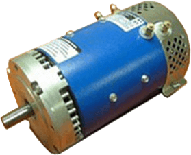
The electric DC motor has two basic parts: the rotating part that is called the armature, and the stationary part that includes coils of wire called the field coils. The stationary part of the electric dc motor is also called the stator.Figure 12-1 shows a picture of a typical DC motor, Fig. 12-2 shows a picture of an electric DC motor armature, and Fig. 12-3 shows a picture of a typical electric dc motor stator. From the picture in Fig. 12-2 you can see the armature is made of coils of wire wrapped around the core, and the core has an extended shaft that rotates on bearings. You should also notice that the ends of each coil of wire on the armature are terminated at one end of the armature. The termination points are called the commutator, and this is where the brushes make electrical contact to bring electrical current from the stationary part to the rotating part of the electric dc motor.
The picture in Fig. 12-3 shows the location of the coils that are mounted inside the stator. These coils will be referred to as field coils in future discussions about the electric dc motor and they may be connected in series or parallel with each other to create changes of torque in the electric dc motor. You will find the size of wire in these coils and the number of turns of wire in the coil will depend on the effect that is trying to be achieved.
FIGURE 12-1 : A typical electric DC motor.
FIGURE 12-2 : The armature (rotor) of an electric DC motor has coils of wire wrapped around its core. The ends of each coil are terminated at commutator segments located on the left end of the shaft. The brushes make contact on the commutator to provide current for the armature.
FIGURE 12-3 : The stationary part of a electric DC motor has the field coils mounted in it.
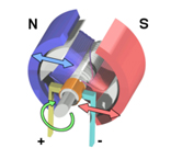
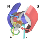
It will be easier to understand the operation of the electric DC motor from a basic diagram that shows the magnetic interaction between the rotating armature and the stationary field's coils. Figure 12-4 shows three diagrams that explain the electric DC motor 's operation in terms of the magnetic interaction. In Fig. 12-4a you can see that a bar magnet has been mounted on a shaft so that it can spin. The field winding is one long coil of wire that has been separated into two sections. The top section is connected to the positive pole of the battery and the bottom section is connected to the negative pole of the battery. It is important to understand that the battery represents a source of voltage for this winding. In the actual industrial-type motor this voltage will come from the DC voltage source for the motor. The current flow in this direction makes the top coil the north pole of the magnet and the bottom coil the south pole of the magnet. Typical electric dc motor voltages are as follows: 24 volt dc motors, 24 v dc motor, 36 v dc motor, 12 volt dc motor, and 72 volt electric motor.
The bar magnet represents the armature and the coil of wire represents the field. The arrow shows the direction of the armature's rotation. Notice that the arrow shows the armature starting to rotate in the clockwise direction. The north pole of the field coil is repelling the north pole of the armature, and the south pole of the field coil is repelling the south pole of the armature.
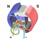
FIGURE 12-4 (a) : Magnetic diagram that explains the operation of an electric DC motor. The rotating magnet moves clockwise because like poles repel. (b) The rotating magnet is being attracted because the poles are unlike. (c) The rotating magnet is now shown as the armature coil, and its polarity is determined by the brushes and commutator segments.
As the armature begins to move, the north pole of the armature comes closer to the south pole of the field, and the south pole of the armature is coming closer to the north pole of the field. As the two unlike poles near each other, they begin to attract. This attraction becomes stronger until the armature's north pole moves directly in line with the field's south pole, and its south pole moves directly in line with the field's north pole (Fig. 12-4b).
When the opposite poles are at their strongest attraction, the armature will be "locked up" and will resist further attempts to continue spinning. For the armature to continue its rotation, the armature's polarity must be switched. Since the armature in this diagram is a permanent magnet, you can see that it would lock up during the first rotation and not work. If the armature is an electromagnet, its polarity can be changed by changing the direction of current flow through it. For this reason the armature must be changed to a coil (electromagnet) and a set of commutator segments must be added to provide a means of making contact between the rotating member and the stationary member. One commutator segment is provided for each terminal of the magnetic coil. Since this armature has only one coil, it will have only two terminals, so the commutator has two segments.
Since the armature is now a coil of wire, it will need DC current flowing through it to become magnetized. This presents another problem; since the armature will be rotating, the DC voltage wires cannot be connected directly to the armature coil. A stationary set of carbon brushes is used to make contact to the rotating armature. The brushes ride on the commutator segments to make contact so that current will flow through the armature coil.
In Fig. 12-4c you can see that the electric DC motor voltage is applied to the field and to the brushes. Since negative electric DC motor voltage is connected to one of the brushes, the commutator segment the negative brush rides on will also be negative. The armature's magnetic field causes the armature to begin to rotate. This time when the armature gets to the point where it becomes locked up with the magnetic field, the negative brush begins to touch the end of the armature coil that was previously positive and the positive brush begins to touch the end of the armature coil that was negative. This action switches the direction of current flow through the armature, which also switches the polarity of the armature coil's magnetic field at just the right time so that the repelling and attracting continues. The armature continues to switch its magnetic polarity twice during each rotation, which causes it to continually be attracted and repelled with the field poles.
This is a simple two-pole electric DC motor that is used primarily for instructional purposes. Since the motor has only two poles, the electric DC motor will operate rather roughly and not provide too much torque. Additional field poles and armature poles must be added to the electric DC motor for it to become useful for industry. (24 volt dc motors, 24 v dc motor, 36 v dc motor, 12 volt dc motor, and 72 volt electric motor)
21. Why is it that many pump motors use tang drivers?
Pump motors often use tang drives because they provide a simple, efficient and reliable way to transfer torque from the motor to the pump. Here are some key reasons why they are commonly used:.
1. Easy alignment and Assembly
Tang drives allow for easy self-centering and quick connection between the motor and pump, reducing the complexity of installation and maintenance.
2. Cost-Effective & Durable
The design of a tang drive is mechanically simple, making it cheaper to manufacture and maintain compared to more complex couplings. It also minimizes wear over time.
3. Efficient Torque Transfer
Tang drives provide a direct, positive engagement, ensuring efficient torque transfer without slippage. This is especially useful for applications that require a consistent and reliable power transmission.
4. Designed for High-Speed and High-Load Applications
Pump motors often operate at high speeds and under varying loads. Tang drives can handle high torque and rotational speeds while maintaining efficiency.
5. Prevents Overloading and Misalignment issues
Unlike rigid couplings, tang drives can tolerate slight misalignments, preventing excessive stress on the motor shaft and pump components. This helps extend the life of the equipment
6. Common in Hydraulic and Fluid Pumps
Tang drives are widely used in hydaulic pumps, fluid transfer systems, and industrial applications due to their ability to withstand high pressures and demanding operational conditions.
22. How can I make my golf cart faster?
The number one thing to understand is that the majority of golf carts floating around after market were built by EZGO, Club Car, or Yamaha. They were mainly built for golf course applications. Therefore, as actions are taken to enhance the carts speed and/or torque, certain weak links in the design can fail. There is potential for grave bodily harm, injury, or death if products are used in the wrong application.
D&D motor systems is the ONLY company in the world who has developed a proprietary choose a
motor tool that
asks the customer several critical questions about the golf cart make, model, and year; the application the
cart is being used in;
and the customer's performance requirements.
We then calculate maximum current draw along with the system's max thermal rating to ensure the customer
will be safe.
If a product line option does not show up for purchase then it means the safety risk to the customer is too
high.
With that being said, below are the main ways to increase the speed of a golf cart.
23. Upgrade to a high speed golf cart motor
The ONLY golf cart electric motor made in the USA is manufactured by D&D Motor systems, INC. in Syracuse, NY (95% of the motors components come from the USA!!!) . No manufacturer in the world provides more golf cart motor options than D&D Motor Systems. Just click on this link and answer a few questions about your golf cart application and performance requirements. You will then be presented with many options from least expensive and lowest performing at the top to more expensive and highest performing options at the bottom. We also offer slightly blemished products at a discounted price but with the same warranty.
24. Upgrade to a high speed controller
BEWARE - You can only increase speed output of a golf cart controller upgrade if your cart is a SEPEX/Regen cart (separately excited cart regenerative braking) Find out how to tell here! The amount of additional speed you will get out of an upgraded Regen controller will depend on the controller amperage and the Regen controller programming. Field mapping is critical and if not uploaded properly may cause the motor to fail and the desired performance to fall short. If you buy an upgraded controller through D&D Motor Systems, by clicking on this link we will ensure your controller is properly programmed.
No matter what type of cart you have, if you increase the controller amperage you will gain additional torque and controller thermal capability (less likely to burn up!). Torque is your pick-up out of the gates and your pulling power, it is not top end speed!!!
25. Increase the diameters of my tire
Normal stock golf carts have 10 inch Diameter tires. If you upgrade to 23 inch tires you can expect an speed increase of about 2-3mph. BEWARE - when you install those larger 23 inch tires you are raising the profile of the cart and it will not handle as well in the turns. In addition your tire thread is critical in calculating the coefficient of friction between your tire and the ground. The traction is critical in determining how your golf cart ride is going to feel. Ensure you choose the thread that best fits your applications. Any reputable golf car dealer can steer you in the right direction with regards to that choice.
26. Increase the voltage of my cart from 36V to 48V
By increasing the voltage of the batteries in your cart from 36V to 48V you will normally increase your cart speed by about 4mph. The negative if you have to cough out the dough for the batteries and new battery charger. Therefore, we recommend if your going to do this procedure, wait until you are going to have to buy new batteries anyways. There are a bunch of videos online that show you how to do that. A few of the videos can be found below.
Lastly if your cart is not being properly maintained you will lose performance. Use this link to ensure you are staying up to date on key maintenance asks.
27. Increase the gearing of my cart
The approximate gearing of a typical golf cart axle is around 12.44:1. The two main ones used are Dana (EZGO & Yamaha) and Graziano (Club Car). By installing a lower gear ratio such as 8:1 or 6:1 you will increase your speed and current draw. The negative is that your torque will go down. In addition depending on your vehicle setup and application you may need to upgrade your motor, controller, solenoid, forward and reverse/switch, and wires. 6:1 gears should gain you about 50% more speed where as 8:1 gears will gain you about 33% more speed. The negative to the gear changing is they can be a bit of a knuckle buster if you have never done it before and some additional noise can sometimes be heard from the differential. With that said, anyone looking for high-speed gears and you want to buy American, Click this link
28. How is speed controller in a DC motor?
Generally, the rotational speed of a DC motor is proportional to the voltage applied to it, and the torque is proportional to the current. Speed control can be achieved by variable battery tappings, variable supply voltage, resistors or electronic controls. The direction of a wound field DC motor can be changed by reversing either the field or armature connections but not both. This is commonly done with a special set of contactors (direction contactors).
The effective voltage can be varied by inserting a series resistor or by an electronically controlled switching device made of thyristors, transistors, or, formerly, mercury arc rectifiers.
In a circuit known as a chopper, the average voltage applied to the motor is varied by switching the supply voltage very rapidly. As the "on" to "off" ratio is varied to alter the average applied voltage, the speed of the motor varies. The percentage "on" time multiplied by the supply voltage gives the average voltage applied to the motor. Therefore, with a 100 V supply and a 25% "on" time, the average voltage at the motor will be 25 V. During the "off" time, the armature's inductance causes the current to continue through a diode called a "flyback diode", in parallel with the motor. At this point in the cycle, the supply current will be zero, and therefore the average motor current will always be higher than the supply current unless the percentage "on" time is 100%. At 100% "on" time, the supply and motor current are equal. The rapid switching wastes less energy than series resistors. This method is also called pulse-width modulation (PWM) and is often controlled by a microprocessor. An output filter is sometimes installed to smooth the average voltage applied to the motor and reduce motor noise.
Since the series-wound DC motor develops its highest torque at low speed, it is often used in traction applications such as electric locomotives, and trams. Another application is starter motors for petrol and small diesel engines. Series motors must never be used in applications where the drive can fail (such as belt drives). As the motor accelerates, the armature (and hence field) current reduces. The reduction in field causes the motor to speed up until it destroys itself. This can also be a problem with railway motors in the event of a loss of adhesion since, unless quickly brought under control, the motors can reach speeds far higher than they would do under normal circumstances. This can not only cause problems for the motors themselves and the gears, but due to the differential speed between the rails and the wheels it can also cause serious damage to the rails and wheel treads as they heat and cool rapidly. Field weakening is used in some electronic controls to increase the top speed of an electric vehicle. The simplest form uses a contactor and field-weakening resistor; the electronic control monitors the motor current and switches the field weakening resistor into circuit when the motor current reduces below a preset value (this will be when the motor is at its full design speed). Once the resistor is in circuit, the motor will increase speed above its normal speed at its rated voltage. When motor current increases, the control will disconnect the resistor and low speed torque is made available.
One interesting method of speed control of a DC motor is the Ward Leonard control. It is a method of controlling a DC mo
29. Pros and Cons of Gas vs Electric Motors
What are the pros and cons of Gas Golf Carts?
Gas Pros
- Quick Refuels
- Longer Range
- Less dependency on Charging Infrastructure
Gas Cons
- Very Noisy
- High Emissions
- Requires much more maintenance
- Fuel costs are much greater than that of electricity
What are the pros and cons of Electric Golf Carts?
EV Pros
- Environmentally friendly and quiet operations
- Lower Maintenance Costs
- Provides a much smoother driving experience
EV Cons
- Limited range and requires charging
- Requires charging which can take longer than refilling
- Battery replacement can be costly after a few years
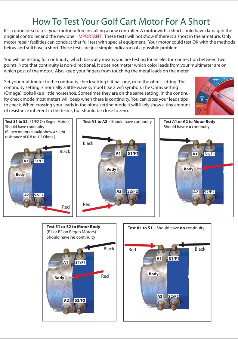
30. How to test your golf cart motor for a short
31. 4 AWG golf cart wire kits specifications
— 420 strands of 30 gauge (AWG) 100% copper in each golf cart cable
— Each golf cart cable is crimped, then soldered and shrink-wrapped.
— Each terminal has color-coded shrink wrap
— Terminals are made from solid copper and then tin-coated for superior corrosion resistance
— 600 Volt capacity golf cart cable
— Very flexible and easy to install
— Easily readable wiring diagrams and packing list are included
D&D Motor Systems stocks a complete line of golf cart cables as listed below. Replacing a golf cart wire kit allows the golf car cables to carry more current (amps) thus enhancing performance. The stock vehicles come equipped with a 6 AWG golf cart wire kit, which may be fine for basic golf course use. However, our upgraded high-performance 4 AWG golf cart cables reduce resistance caused by the higher current draw in performance upgrades. Golf cart cables can overheat or melt in heavy-duty applications, commonly due to loose terminal connections, which cause resistance and heat buildup.
EZ-GO: Series 1996 and Up - Pictured Below
(All other golf cart cables are similar except lengths and quantities)

EZ-GO: DCS and PDS - Pictured Below
(All other golf cart cables are similar except lengths and quantities)

Club Car: IQ - Pictured Below
(All other golf cart cables are similar except lengths and quantities)

Made in the USA
The only DC Motors Manufacturer in America
Fast, Reliable Shipping
We provide fast 2-3 day shipping in the USA
Engineering Expertise
Unparallel customer support from our expert engineers