Browse
Dealer
High Performance DC Motors and Controllers
Buy a Golf Motor/
Golf Controller
Technical / Troubleshooting Tips
Golf Cart Motors
- 1. Increase the efficiency of a DC motor
- 2. Disassemble a golf cart axle
- 3. Reset Onboarding Computer (OBC) of a series motor
- 4. Speed Sensor Test Procedure: Cart is starting fast but slows down quickly
- 5. How do I fix noise coming from my Motor or Axle area?
Club Car
EZGO
Yamaha
Golf Cart Controller
- 8. How to test a cart controller
- 9. How to troubleshoot a controller on a Regen Cart
- 10. Diagnose a golf cart with a malfunctioning controller
Club Car
EZGO
Yamaha
Maintenance Tips
1. Increase the efficiency of a DC motor
There are quite a few things to you can do to increase the efficiency of a DC motor. Here are a few of them:
Maintenance:
Regular inspections, lubrication, and the cleanness of your motor can all have an impact. Always make sure
your motor is as clean as possible and that its components don't have too much wear and tear. This includes
things such as its brushes and commutators, as well as electrical connections and insulation.
Temperature management:
The name of the game is keeping cool. High heats can cause damage to your motor. The keyto keeping a motor
cool is to choose a motor with enough
steel and copper. This can be done by using our "Choose a Motor Tool".
If possible we recommend using ventilation, internal or external fans, or a heatsink. Any bit helps but the
important thing
is keeping it cool!
High Quality Components:
Though this may feel obvious finding the right components can make a huge difference. Look for high quality
copper windings, bearings, and lubricants. As well as high quality electrical steel in the lamonticns with
minimal care loss. If you want to know your finding the best possible motor for your specific needs you can
use our custom built "Choose a Motor Tool".
Keep the rotor and stator close together:
Precision is key, keeping a small gap between the rotor and stator without letting them touch can increase
efficiency.
2. Disassemble a golf cart axle
We understand sometimes you need to dive into the finer details. Disassembling a golf cart axle can be tricky, but we’re here to help. Follow the step-by-step guide below to get it done:
Tools you’ll need:
-
Wheel Chocks
-
Car Jacks
-
Jack Stands
-
Socket Set
-
Ratchet
-
Needle-Nose Pliers
-
Bearing Puller
-
Park the golf cart on a flat surface. Place the wheel chocks in front of the front wheels. Jack up the rear end of the cart, then set two jack stands underneath to support it with the rear tires off the ground.
-
Remove the bolts holding the rim onto the hub and pull off the tire and rim.
-
Take off the cover of the drum brake and remove the bolts securing it to the hub.
-
Use needle-nose pliers to pull out the "C" clip, which you’ll find visible through the hole in the flange. Pull the hub away from the axle.
-
Attach the bearing puller to the center of the axle and secure its arms around the rear bearing housing. Tighten the puller until the bearing comes free.
-
Finally, pull the axle out of the golf cart by hand.
3. Reset Onboarding Computer (OBC) of a series motor
-
Unplug the positive and negative connections from the battery pack
-
Put the cart to reverse
-
Push the accelerator pedal fully down until the reverse buzzer ceases
-
Reconnect the power supply
4. Speed Sensor Test Procedure: Cart is starting fast but slows down quickly
Ensure that the cart is not in sleep mode. You can do this by driving the cart a short distance. Just verify
that the cart is operational.
With the F&R switch set to any of the three positions and the Tow/Run switch in the Run position, manually
push the cart to simulate a roll-away situation.
The "Roll-Away" braking system will engage to slow the cart down and prevent it from rolling away,
accompanied by a series of beeps from the reverse
buzzer as it decelerates. If the cart rolls freely without any resistance, this indicates a lack of
communication between the cart's speed sensor and
the controller. In this case, there is a speed sensor failure, and it will need to be replaced.
These carts use two different types of motors, each equipped with a distinct speed sensor.
5. How do I fix noise coming from my Motor or Axle area?
Most likely this is caused by wear on interface between the motor shaft and differential gears. This wear no longer causes a
tight fit and that is what is most likely causing your noise. To know more about this click on the video thumbnail below.

6. Remove Regen braking on a Club Car
Simply unplug the motor speed sensor from your motor. Note, this will not work on Club Car IQ Carts!
7. How to identify your yamaha cart
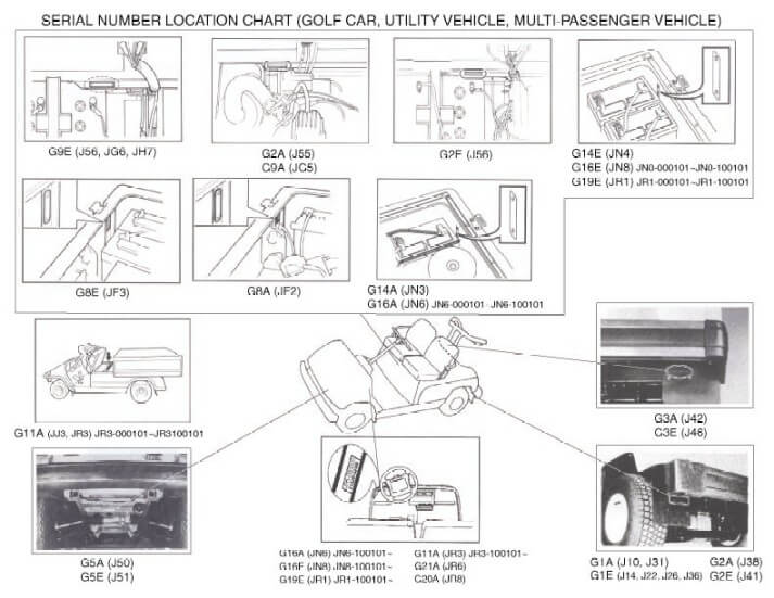
Yamaha Golf Car models typically start with a "G", except for the latest Drive2
model. The model's second digit signifies its age, with higher numbers indicating
newer models.
Models ending in "A" are gas-powered, while "E" signifies electric.
If you're unsure of the type, lift the seat; batteries indicate an electric car,
while a motor and belts signify gas.
A G1 model has two bucket seats, while G2-G9
models feature a bench seat, identifiable by steering column color, access doors,
and sometimes dash panel colors. The G14, G16, and G19 models, introduced later,
display variations in logos and power configurations, such as 36V and 48V options
for electric models.
The G29 "Drive" model, launched in 2007, introduced distinct
design changes, including cup holders, rear downspouts, and in later versions,
EFI and AC systems. The current Drive2 model is visually similar to the G29 but
is distinguishable by the white/gray "Yamaha" logo on the side panels, as well as
a rear body separated into three segments.
If the emblem says Yamaha, your car is a G16. New body style, rounded fenders, Yamaha emblem in
front, gas engine, your car is a G16A. New body style,
rounded fenders, Yamaha emblem in front, electric powered, your car is a G16E or a G19E, both electric cars.
To tell the difference between a G16E, which is a 36Volt electric, versus a G19E, which is a 48 Volt
electric, look for the Forward Reverse Control.
If it is a black switch on the dash, your car is a G19E 48 Volt. If the Forward Reverse is in the center of
the rear body, large black lever,
your car is a G16E 36 Volt electric.
(Exception: it may fit the above description for an electric car and be a G14E, (1995-6) however there
is no appearance difference and no parts difference
between a G14E and a G16E (1996-2002), so for ordering parts it is safe to say the car is a G16E.)
If the car has the new Yamaha "tuning fork" logo on the front cowl, then your car is a G22.
Tuning fork logo, gas engine, G22A. Tuning fork logo, electric powered, G22E.
8. How to test a cart controller
The Controller is the "heart" of the motor, without it, your motor will never operate.
Unfortunately there are many reasons why your tests seem to be getting no where. The important thing to remember
when working on one of these carts is to isolate components. This eliminates flow-through or by-pass voltage
and/or current.
-
First discharge the controller: We want to get all of the energy out of that motor before we start doing anything to it. To do this simply shut down all components (key switch = Off, F&R = Neutral, Tow/Run switch = Tow).
-
Disconnect battery last negative cable at battery pack: Key switch = On, F&R = Reverse, Tow/Run switch = Tow.
-
Depress and hold the accelerator for 30 seconds: Key Switch = Off, F&R = Neutral, Tow/Run = Tow
9. How to troubleshoot a controller on a Regen Cart
We've all been there, and believe us when we say we get it. The Regen controller
is much more complex that the series counter part. Luckily we can share some common issues and tests we have
found
work the best.
Often times we fine when a Regen controller fails its often the feild diodes that have failed in their place.
Almost always when the feild diodes fail its due to the shorted or partically shorted motor. Below you will find
a simple test to
determine if the diodes are what failed:
-
Set the digital meter to 'DIODE MODE'
-
place red (+) probe B-bus bar and the Black (-) on the M- or A1 bus bar. Meter should be reading 0.5V +/- 0.2V
-
Place the Red (+) probe on the M- or A1 bus bar and the Black (-) probe on the B+ bus bar. Meter should be reading 0.5V +/- 0.2V
-
Place the Red (+) probe on the B- bus bar and the Black (-) probe on the F1. Meter should be reading 0.5V +/- 0.2V
-
Place the Red (+) probe on the B- bus bar and the Black (-) probe on the F2. Meter should be reading 0.5V +/- 0.2V
-
Place the Red (+) probe on the F1 and the Black (-) probe on the B+ bus bar. Meter should be reading 0.5V +/- 0.2V
-
Place the Red (+) probe on the F2 and the Black (-) probe on the B+ bus bar. Meter should be reading 0.5V +/- 0.2V
10. Diagnose a golf cart with a malfunctioning controller
The issue with a non-running diagnosis lies in identifying the cause versus the effect. A cause is the action, and the effect is its result. Understanding this distinction is essential to dive deeper into the problem. Knowledge of the system and experience with it are also crucial.
The root of the issue is often the motor. A motor that is shorted, even partially, can lead to controller failure. Installing a new controller with a faulty motor is likely to cause another failure.
When faced with a defective controller, check the motor as outlined in the test below. Even if the motor passes, it’s important to remove it for a visual inspection and a smell test to detect potential issues.
Testing a Regen, Shunt-Wound Motor
When a Regen or Shunt-wound controller fails, it’s often due to a larger underlying issue, commonly a motor short. A shorted motor will damage a newly installed controller if the motor is not addressed first.
1. Discharge the controller circuit.
2. Disconnect F1 and F2 from the controller.
3. Disconnect all cables from the motor.
4. Use an ohmmeter to test the motor:
- A1 to A2: A reading other than “open” is acceptable.
- F1 to F2: A reading between 1 and 3 ohms is acceptable.
- Any continuity from any of the studs to the case indicates a problem.
Note: Some motors label F1 and F2 as S1 and S2 instead.
5. Remove the motor to inspect the windings and brushes.
Even if the motor passes all tests, it may still be defective. If it fails any test, it is likely shorted, and installing a new controller will only result in further damage.
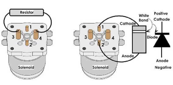
11. How to check your Golf Cart for a bad Solenoid
In this article as you may have guessed I am going to explain how to check a solenoid for problems. First you will need a couple of tools, a voltmeter and typically a ½” wrench.
On a typical solenoid there are four post called terminals. There are usually two large and two small. Battery voltage is applied to the two small terminals to activate the solenoid which then connects the two large terminals together. From time to time the two large terminals get buggered up and the solenoid needs to be replaced. To check the solenoid is fairly simple though.
First thing we need to do is disconnect any cables from the two large terminals. Be sure to wrap the cable ends in tape and keep them separate from each other. Then set your voltmeter to OHMS and place a probe on each large terminals(see first image below). With the key off and the cart in a neutral position there should be no reading. Now with the cart in foreword position and key on step on the accelerator, you should hear a click coming from the solenoid, if you do then set you voltmeter to OHMS and place a probe on each large terminals(see second image below). You should have a reading of 0 to 0.4 ohms. Anything higher and it means that solenoid has buggered up contacts and should be replaced.
If you did not here a click coming from your solenoid then grab your voltmeter and set it to dc volts on the 200 scale and place a probe on each of the small terminals. With the key on and the cart in foreword step on the accelerator. You should see pretty close to full battery voltage. If you do see full battery voltage and there is no click, the coil inside the solenoid has failed and will need to be replaced. If your meter remains at 0 then there is a problem somewhere else in the cart.
NOTES: When buying a new solenoid besure to buy one that matches your carts voltage, most golf carts are either 36v or 48v. It will usally tell you on the side of the solenoid what voltage it is. If you use the D&D Motor Systems Choosing A Motor tool then you can be assured to get the right parts every time.
12. How do I tell if my Golf Cart Solenoid is not working
13. How do I troubleshoot my Solenoid
A) Does the Club Car Solenoid or EZ-GO Solenoid make a
"clicking" sound?
If it doesn't, we must first determine if
activation voltage is present at the small terminals #1 and #2. Connect a voltmeter across the connections
at #1 and #2 and activate the system. To activate the system put the car in the run mode, key switch on, car
in forward and the accelerator pedal pushed. If your voltmeter displays the system voltage and the solenoid
does not "click", then the solenoid is defective and will need to be replaced.
Make the connection just like this.
B) The Golf Cart Solenoid does
not "click" and you do not read system voltage. This tells us that one of the voltage potentials is missing
at connection #1 and or #2. To find out which potential is missing, leave the red lead of the voltmeter
connected on terminal #2, the positive connection (usually a blue or red wire). However, wire colors may
vary. Ensure proper diagnosis by using the correct diagram for the make and year of your car. Place the
black lead of the voltmeter to the battery's negative post on the number six battery (the last battery in
series from the first positive battery connection to the car). Activate the system as before, if your
voltmeter reads system voltage, the positive input is correct. This means the key switch, micro switches and
wiring are good and you are missing the negative input. (Club Car Solenoid)
Positive connection at terminal #2.
Continue the
diagnosis process by connecting the black negative lead from the voltmeter to terminal #1 and the red lead
of the voltmeter to battery #1's positive post (the first positive connection to the car). Activate the
system again. If you are not reading system voltage on your voltmeter, you have confirmed that the battery
negative is missing. Depending on the system the car is using, the missing negative will need to be traced
to its source. Some systems supply the negative from a controller output (or with some Club Car Solenoid, the onboard
computer). Most gas cars use the frame as "ground". Electric cars do not use a frame "ground". You can
determine the car's ground point by referring to the correct wiring diagram.
Negative connection at terminal #1.
So let's say
that we were missing the positive at connection terminal #2. This means either the key switch, micro switch
and/or accelerator switch is open or out of adjustment. NOTE: Be aware that some cars use the key circuit as
a negative circuit and adjust accordingly as per the correct wiring diagram. You will need to trace voltage
to each individual component in that circuit and determine where the voltage is lost.
If your car uses the diode in the solenoid system, make sure you make the proper
connections and orientation as the diode is polarity-sensitive! This is different between the Club Car Solenoid and the
EZ-GO
Solenoid.
Secondary Circuit (power)
1) If the Golf Cart Solenoid does
"click" and the car will not run. Disconnect the cable from terminal #4 and lay it aside. Tape the end so it
doesn't come into contact with any part of your car. Cable 4 will be the load side of the solenoid that
connects directly to the controller/motor circuit. If the car uses a 250-ohm resistor, remove and tape the
end of that as well.
2) Place the positive lead of the
voltmeter on the vacated #4 terminal. Place the negative lead of the voltmeter to battery #6's negative
post. Activate the system. If your voltmeter does not display system voltage, the secondary circuit's
contacts are defective and the solenoid will need to be replaced. If you do read system voltage on your
voltmeter the problem with your car is somewhere in the controller, motor, wiring/cables, shifter and/or
input control, such as an inductive throttle sensor, potentiometer, or v-glide.
3) If the Golf Cart Solenoid does not "click" and the car runs all
the time with the key on or off. Connect the voltmeter as per step number two. If you read system voltage
without pushing the accelerator pedal and key off the solenoid is defective. This means the secondary
contacts are stuck in the "on" position and the solenoid needs replacement.
Safety
1) Raise the rear wheels off the ground
using the proper support stands BEFORE you begin your Golf Cart Solenoid testing.
2) Disconnect the battery/battery pack when required for testing. If the car is a
regenerative system, place the run/tow switch in the tow position before you disconnect the
batteries.
3) If you have a proclivity towards being a
pyromaniac, make sure you know where the closest fire extinguisher is!
4) Use extreme caution with higher voltage cars as severe burns can occur by
accidentally shorting out connections with a hand tool.
5) Golf
Cart Solenoids testing should be done in a well-ventilated area and extreme
caution used around the batteries as hydrogen gas may be present.
6) Keep all flames and sparks away from the battery compartment and keep battery
acid away from your skin and eyes as this can be an irritant.
There you have it! The solenoid is not some complicated mystery. Just think of it as
just any other switch you may encounter that it is electrically activated.
14. How to Wire a Golf Cart Battery
| 1. | Open the battery compartment of your golf cart by lifting the seat out of the cart. Golf cart battery banks are normally located beneath the seat of the cart. |
| 2. | Remove the black negative cable from the first battery in the bank followed by the subsequent positive wire. You will do this for each battery in the bank in the same order moving from forward to rear in the battery bank. |
| 3. | Lift the batteries that require removal from the battery bank. Some battery banks are designed to hold each battery in place with a battery clip that will require a basic wrench to remove the securing nut and washer from the bracket. |
| 4. | Place the new batteries into the bank in the same position the battery that you removed was sitting. Re-secure the securing brackets for each new battery. |
| 5. | Reconnect the battery cables to the batteries in the bank. The main positive lead for the battery bank coming from the frame of the cart will connect to the positive terminal of the first battery in the bank. Then, connect a cable from the negative terminal of the first battery to the positive terminal of the subsequent battery in the bank. Continue connecting the negative terminal to the next positive terminal until all batteries are connected. The last battery in the bank will have a connection from its negative terminal to that of the frame or golf cart controls. |
| 6. | Connect the reverse positive cable to any of the positive terminals on the battery bank. This will be the extra positive cable that you disconnected when removing the batteries. This is the cable that powers the engine when the cart moves in reverse. |
Maintenance Tips
15. Maintaining your cart for maximum performance
Regular upgrades to your D&D Motor Systems motor can drastically improve the results of your cart.
16. Sticking or dragging brakes
Caused by dirt in brake cable housings, dust or oil on brake shoes, affecting brake release.
17. Improper wheel alignment
Wheels should have 1/4-inch toe-in; the distance from the front should be slightly shorter than the back to ensure proper alignment.
18. One or more weak batteries
Batteries need the correct water level (1/4 inch above plates) and should be checked with a load tester to ensure consistent performance across all batteries.
19. Bad, worn or loose battery cables
Corroded or worn battery cables should be cleaned or replaced, as they can disrupt battery function.
20. Dirty F&R switch
Clean or replace the F&R switch if contacts are dirty, as it can affect performance.
21. Improperly Adjusted V-glide linkage
Ensure the V-glide wiper brush reaches its full range when the accelerator is pressed and is level on contact pads.
22. Wheel bearing drag
Bearings should be clean and well-greased without overtightening to avoid wheel drag.
23. Leaking axle seals
Oil leaks onto brake shoes can cause dragging; replace seals and clean or replace shoes as needed.
24. Improper tire pressure
Underinflated tires (run at 25 psi) can reduce cart speed, so keeping proper tire pressure is essential.
25. Overheating motor
Lack of airflow can cause motor overheating, leading to insulation breakdown; adequate airflow keeps it cool.
26. Bad motor bearings
Worn bearings can cause armature drag, leading to excess noise and reduced performance.
27. Badly worn or sticking brushes
Carbon dust buildup can prevent proper contact with the armature, causing poor motor performance.
Made in the USA
The only DC Motors Manufacturer in America
Fast, Reliable Shipping
We provide fast 2-3 day shipping in the USA
Engineering Expertise
Unparallel customer support from our expert engineers